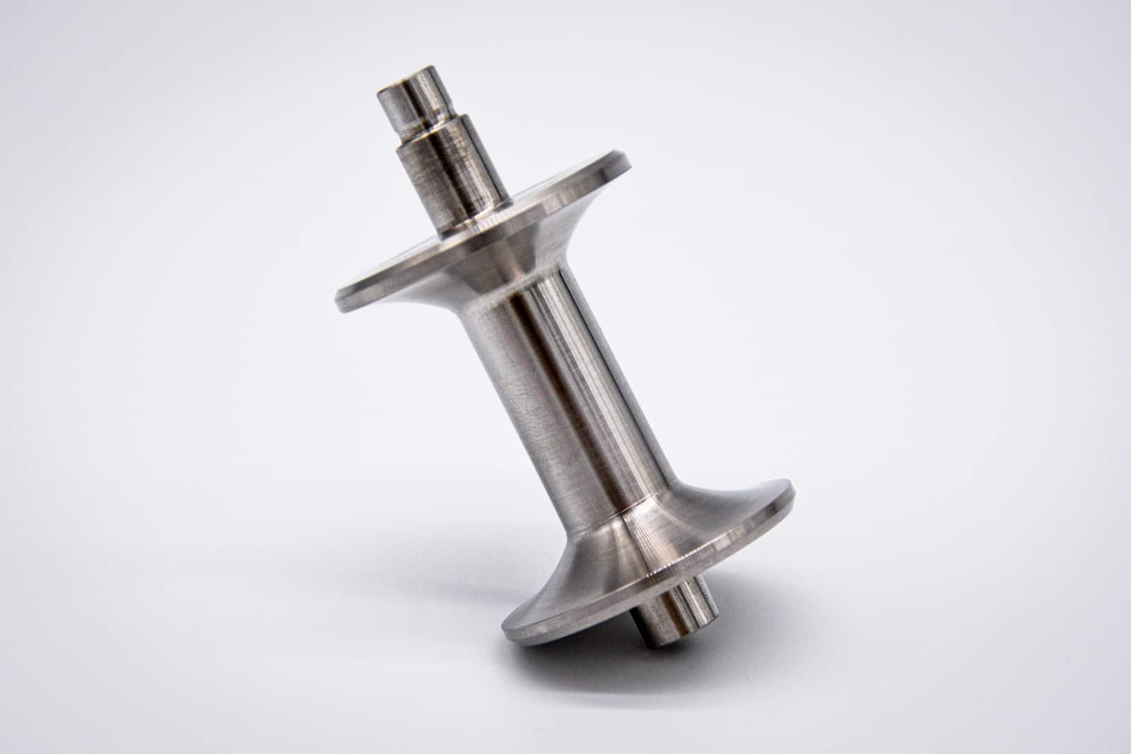
Direct Metal Laser Sintering (DMLS), also known as Direct Metal Laser Melting (DMLM), is a group of metal 3D printing technologies that use a high-powered laser to fuse metal powder into solid parts layer by layer. DMLS allows for the creation of highly detailed, complex metal components with exceptional precision, ideal for producing intricate geometries and fine features that are difficult to achieve through traditional manufacturing methods.
To fully harness the capabilities of DMLS, it is crucial to avoid common mistakes by following specific design guidelines and best practices, such as incorporating adequate support structures, determining optimal wall thicknesses, and maintaining proper distances between features.
These considerations, among others, will be discussed in detail in this guide to help you optimize your designs for successful DMLS 3D printing.
#1 Misuse or Overuse Support Structures
In Direct Metal Laser Sintering (DMLS), each printed layer relies on the previous layers for support. For geometries like overhangs, arches, and surfaces angled greater than 30°, additional support structures are necessary to prevent warping, secure parts to the build platform, and maintain accuracy during printing. These supports, although crucial, increase material usage, build time, and costs, and must be removed in post-processing.
Rule of thumb:
- Design self-supporting features with angles of 45° or more to reduce the need for support structures.
- Minimize the need for supports by using angles of 30° or less and adding fillets or chamfers on corners.
- Provide adequate support for horizontal surfaces, large holes, and overhangs to prevent part movement during printing, which can cause inaccuracies or machine crashes.

#2 Apply Inconsistent or Insufficient Wall Thicknesses
Wall thicknesses in metal 3D printing can vary based on material choice, part orientation, and desired resolution. Thicker walls enhance the structural integrity of the part and are a best practice in most designs.
Rule of thumb:
- Maintain a minimum wall thickness of 0.8 mm for general designs to reduce breakage risk.
- Use 1 mm thickness for supported walls (connected to two or more sides) and 1.2 mm for unsupported walls (connected on only one side or edge) to ensure structural stability and print accuracy.
- Keep a consistent wall thickness

#3 Design Large Overhangs Without Support
Overhangs are abrupt changes in a part’s geometry, differing from self-supporting angles, which have smoother slopes. Overhangs greater than 0.5 mm typically require additional support to prevent damage or deformation during printing. It is advisable not to push the limits with large overhangs, as they can lead to a rougher surface finish, reduced resolution, or even cause the entire build to fail.
Rule of Thumb:
- Add supports for overhangs exceeding 0.5 mm in length or with angles greater than 45 degrees to prevent part deformation and ensure a smoother finish.
- Incorporate chamfers or fillets to overhanging geometries to make them more self-supporting and reduce the need for additional supports.

#4 Improperly Shaping Internal Channels and Holes
One of the key advantages of Direct Metal Laser Sintering (DMLS) is the ability to create complex internal channels and holes that are difficult or impossible to achieve with traditional manufacturing methods. Conformal channels are particularly beneficial, providing uniform cooling throughout a part and reducing its overall weight.
Rule of thumb:
- Limit channel diameters to 8 mm and use tear drop or diamond shapes to minimize distortion and improve surface finish.
- Design holes with a minimum diameter of 1 mm to avoid fusion, and use tear drop shapes for holes not aligned with the build direction to reduce the need for supports.
- Ensure support-free printing for holes between 0.5 mm and 6 mm, while diameters above 6 mm may require orientation adjustments or supports.
- Post-process any hole less than 1 mm for better precision.

#5 Creating Bridges With Overly Long Spans
A bridge in DMLS is a flat, downward-facing surface supported by two or more features. Due to the stresses from rapid heating and cooling in the DMLS process, if the unsupported distance for a bridge is too long, it can result in poor quality on downward-facing surfaces and compromised structural integrity.
Rule of Thumb:
- Limit unsupported bridge spans to 2 mm to maintain structural soundness and surface quality.
- For longer spans, consider adding additional supports or redesigning the bridge with a slight curvature to reduce stress.

#6 Build Narrow Pins and Small Details
Pins, or columns, are tall, thin features with a circular cross-sectional area.
Rule of Thumb:
- Design pins with a minimum diameter of 1 mm to ensure structural stability and reduce the risk of breakage.
- Avoid using diameters smaller than 0.8 mm unless post-processing reinforcement is planned.

#7 Place Features Too Close Together
In DMLS, the heat from the laser causes a melt pool slightly larger than the laser’s diameter, which can cause features that are too close together to fuse or result in unsintered powder trapped between sintered areas.
Rule of Thumb:
- Maintain at least 0.5 mm spacing between features to avoid fusion and ensure proper part formation.
- Ensure a minimum clearance of 0.5 mm for moving parts and 0.3 mm for press fits to avoid bonding and ensure functionality.
- Provide a gap of at least 0.6 mm for printed linkages to prevent sticking and allow smooth operation.

#8 Forget Escape Holes in Hollow Parts
Designing parts to be hollow can significantly reduce material usage and the weight of the final product without compromising functionality. However, for hollow parts, it’s essential to include escape holes to allow the removal of residual unsintered powder from the internal cavities.
Rule of Thumb:
- Design escape holes with a diameter of 2-5 mm to ensure effective removal of unsintered powder from hollow parts.
- Position escape holes on non-visible surfaces and space them apart to facilitate powder circulation and removal.
- Avoid clustering escape holes; instead, place them near edges or on opposite sides of the part for optimal powder evacuation.

#9 Undersize Embossed and Engraved Details
To ensure visibility and clarity in DMLS printing, both embossed and engraved details need to be designed with sufficient size. Embossed features that are too small may not print correctly or may lack definition, while engraved details can close up and become invisible due to heat dissipation into the surrounding powder. For best results, design embossed features larger than the minimum dimensions and ensure engraved details are deep and wide enough to maintain their visibility and definition.
Rule of Thumb:
- Design embossed features with a minimum height of 0.3 mm to ensure they are visible and well-defined.
- Use a text size of at least 14pt for clear, legible embossing.
- Design engraved details with a minimum depth and width of 0.5 mm to maintain visibility and definition.
DMLS Technology Specifications Reference Guide
Below is a quick reference guide summarizing the key specifications and limitations of DMLS technology.
| Specification | Details |
| Maximum build volume | 250 x 250 x 325 mm |
| Minimum feature size | 1.5 mm (structural features) 0.75 mm (cosmetic features) |
| Layer thickness | 0.02 – 0.08 mm (material-dependent) |
| General tolerances | ±0.2% (0.1 – 0.2 mm)* |
| Surface structure | Porous |
| Support structure | Required |
*Producing tight tolerances increases manufacturing costs, so it’s best to apply them only to critical features, such as mating surfaces or components designed to fit with other parts. Additionally, factors like internal stresses during printing, the need for support structures, and part geometry can cause deviations in tolerances and affect flatness. If your design requires strict flatness, DMLS might not be the most suitable option.
Get Your Custom Metal 3D Printed Parts at Xometry
At Xometry, we offer on-demand DMLS 3D printing services across a range of metal alloys through our vast network of manufacturers. After optimizing your model using the design tips provided in this guide, simply upload your file to our Instant Quoting Engine to receive a quote in seconds. Whether you need high-precision prototypes or production-grade metal parts, our advanced DMLS capabilities can bring your designs to life with quality and precision.
Do you have any other experience with designing for DMLS? Share it in the comments!
 Europe
  Türkiye
  United Kingdom
  Global

 Login with my Xometry account
  1
1


Comment(1)