Europe
  Türkiye
  United Kingdom
  Global


Forum Replies Created
-
 Nikolaus Mroncz27.03.2026 at 09:03Xometry Engineer
Hi Prathamesh, thanks for your message.
To avoid a grainy surface it starts with the print orientation, further with condition and parameter of the machine. Also your powder condition will improve. After printing, if the part design allows, I would recommend tumbling. Here, different media leads to different results . If this is not available the classic needs to follow, which is manual post processing. For leakage proof, it needs to be a stable process but also wall thickness. You see, there are many topics. If you like discuss this in detail, don’t hesitate to sign up and book a personal meeting.
https://get.xometry.eu/sign_up
I would gladly discuss your points and answer your questions.best
Niko
0 Nikolaus Mroncz20.01.2025 at 14:40Xometry EngineerHey, if you want to stick on plastic, I would prefer SLS and PA12 or if budget allows, PA11. To achieve accuracy, processing is the right way. Meaning to do, like you did, printing the part, measuring and if it’s not good to reprint, but it must be in the same technology, material and machine
0in reply to: Gearing Nikolaus Mroncz17.01.2025 at 12:45Xometry Engineer
Hey Pulido,
sure you can. The diameter is not the problem, Material is best in stainless 316.
BR
0in reply to: Gearing
Nikolaus Mroncz09.01.2025 at 16:54Xometry EngineerThis is a screenshot of Xometry Pro, where you can find nice design tips for every Tech
0in reply to: Joint Design
Nikolaus Mroncz09.01.2025 at 16:51Xometry EngineerYes, you can print it in one part. The gap should be 0.5mm. SLS or MJF in Nylon is fine
0in reply to: Joint Design
Nikolaus Mroncz09.01.2025 at 16:51Xometry EngineerYes, you can print it in one part. The gap should be 0.5mm. SLS or MJF in Nylon is fine
0in reply to: Joint Design
Nikolaus Mroncz09.01.2025 at 16:51Xometry EngineerYes, you can print it in one part. The gap should be 0.5mm. SLS or MJF in Nylon is fine
0in reply to: Joint Design
Nikolaus Mroncz09.01.2025 at 16:51Xometry EngineerSí, puedes imprimirlo en una sola pieza. La brecha debería ser de 0.5mm. SLS o MJF en Nylon está bien
0in reply to: Diseño de articulación
Nikolaus Mroncz09.01.2025 at 16:51Xometry EngineerEvet, bunu tek parça halinde basabilirsiniz. Boşluğun 0.5mm olması gerekiyor. Naylon malzemesi için SLS veya MJF kullanabilirsiniz
0in reply to: Eklem Tasarımı
Nikolaus Mroncz09.01.2025 at 16:51Xometry EngineerJa, Sie können es in einem Teil drucken. Der Spalt sollte 0,5mm betragen. SLS oder MJF in Nylon ist in Ordnung
0in reply to: Gelenkkonstruktion
Nikolaus Mroncz09.01.2025 at 16:51Xometry EngineerOui, vous pouvez l’imprimer en une seule pièce. L’écart doit être de 0,5mm. L’utilisation de SLS ou MJF en Nylon est acceptable
0in reply to: Conception d’articulation
Nikolaus Mroncz09.01.2025 at 16:51Xometry EngineerSì, puoi stamparlo in un unico pezzo. Lo spazio dovrebbe essere di 0,5mm. SLS o MJF in Nylon vanno bene
0in reply to: Progettazione di giunti
Nikolaus Mroncz09.01.2025 at 16:51Xometry EngineerYes, you can print it in one part. The gap should be 0.5mm. SLS or MJF in Nylon is fine
0in reply to: Joint Design
Nikolaus Mroncz08.01.2025 at 09:48Xometry EngineerHey Pulido, thanks for your question! PP is a very rigid material. Better to take a Nylon to have a good clip function. In the datasheet it is the value elongation of break, which needs to be higher. Unfortunately FDM is a Tech where it is weaker in Z-direction. For a proper part, I would choose MJF or SLS and Nylon 12. Nylon 12 is also available in FDM, but with lower properties
0in reply to: Polypropylene
Nikolaus Mroncz05.11.2024 at 15:23Xometry EngineerHey David, the 3D printed molds have their limitations. In my opinion one of the biggest is the heat transfer. There you work in plastics, it is quite bad and this leads to a long process cycle or sometimes errors in the outcome. It is really for prototyping. Best would be heat resistant material in SLA. My recommendation is to compare the prices on xometry.eu
Maybe CNC could be a better option. You can choose different technologies and materials and see the price difference immediately. In Alu you have constant good outcome.
BR
0in reply to: 3D printed molds for lost wax casting
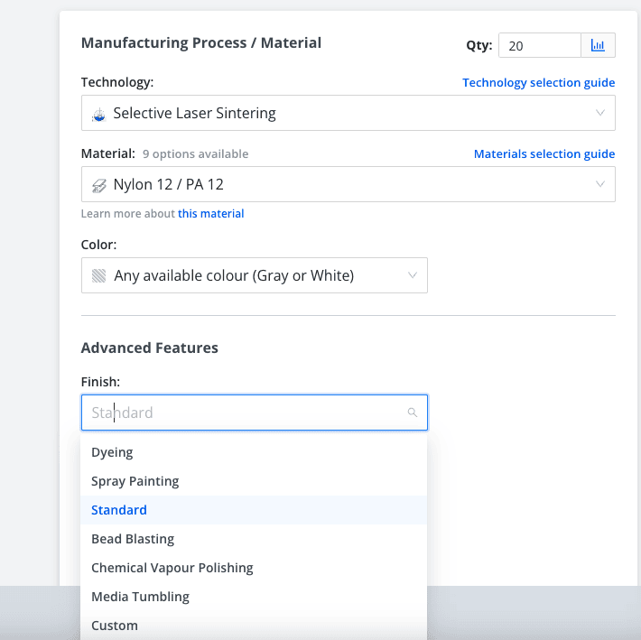
Nikolaus Mroncz05.11.2024 at 09:22Xometry EngineerHey hi, spray painting you can find under finish, like here:
0in reply to: SLS Nylon 12 Paint Color Options
Nikolaus Mroncz28.10.2024 at 11:43Xometry EngineerHey, hi, unsupported channels from 1 to 6mm are in general no problem. If it is smaller, like in your case, it could be challenging and there is no general answer possible and also it should be rated by seeing the whole design. You could also mail me directly under nmroncz@xometry.de
0 Nikolaus Mroncz02.08.2024 at 07:57Xometry EngineerHello Rudolf,
here you will find a guide to convert STL to STEP.
VG
Automatically translated from: DeutschSee original1in reply to: Tips for converting from STL to STEP?
1
Nikolaus Mroncz24.07.2024 at 16:46Xometry EngineerHi David, I never heard of a significant difference in properties and orientation in SLA. Where a bigger difference is, is the curing after the printing. It changes the properties and this information, you can find in the datasheets. More important to know in SLA is, that the properties are just temporary, cause resin parts are aging fast and are quite UV sensible. BR
-
This reply was modified 1 year, 8 months ago by
 Nikolaus Mroncz.
1 Nikolaus Mroncz15.07.2024 at 12:35Xometry EngineerHello Max,
unfortunately, it’s not possible to represent such large parts with flexible materials like Flexible 50A. The material is suitable for the machines Form 3 and Form 4. Form 4 is the larger one and measures 200x125x210mm, which I also see as the maximum. VG
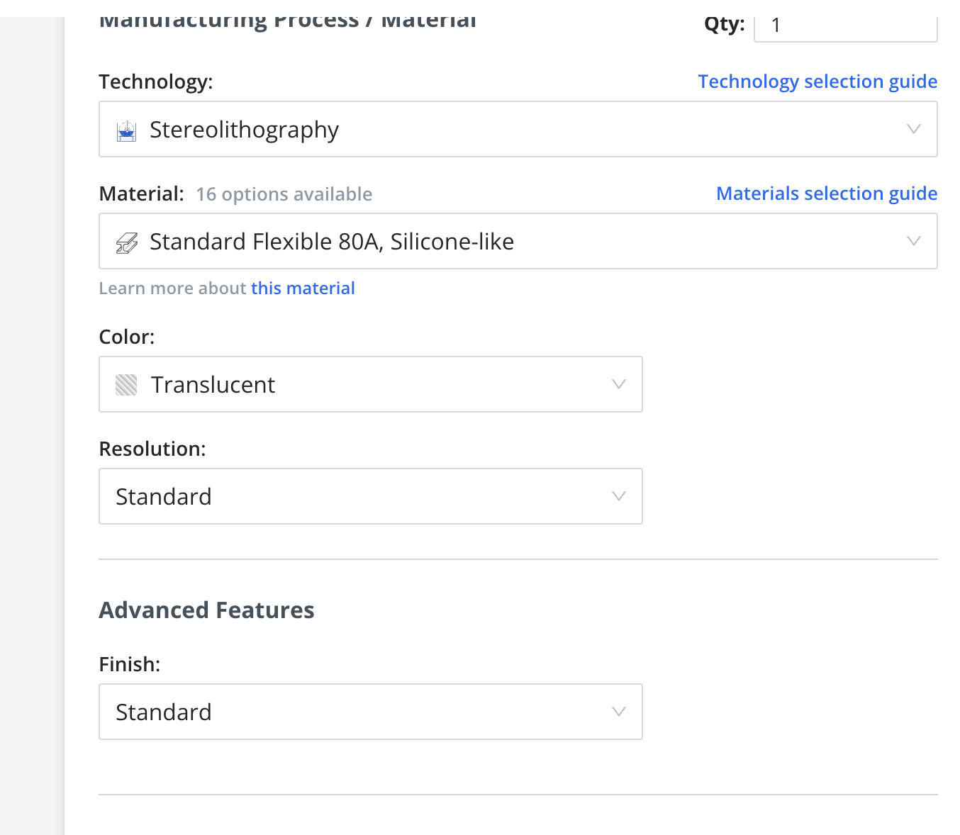
Automatically translated from: DeutschSee original0 Nikolaus Mroncz12.07.2024 at 16:24Xometry EngineerHi Frederico,
the SLA translucent is good to make first trails, to sterilize and reuse might be challengin,g there I expect the material to age quite fast. For this kind of applications injection molded parts are best.
BR
0in reply to: Material Information
Nikolaus Mroncz20.06.2024 at 15:42Xometry EngineerHello Mr. Meyer,
for precise parts, I would definitely prefer SLS. Here you can safely process parts. Even the basic accuracy is already very good. Xometry also offers free project consultation for corporate customers. You could then discuss your specific project, start test parts, try these out and change them if necessary, before you go into a higher quantity. The customer does not need to take shrinkage into account. The manufacturing process is designed to achieve nominal masses, there are slight deviations here, which can then be corrected in another run.
Best regards
Niko
Automatically translated from: DeutschSee original0in reply to: 3D Printing Tolerances for Assembly
Nikolaus Mroncz17.06.2024 at 10:52Xometry EngineerMaximilian LangHey Max,
which process is best for you also strongly depends on the design and quantity of your parts.
Unfortunately, I can only recommend the Polyjet for prototype manufacturing, as hard and soft components do not have the best adhesion and are only short-term when used. I would try the TPU version.
Overmolding would be an option, one would need to compare accordingly, which is more economical.
Best regards
Niko
Automatically translated from: DeutschSee original0 Nikolaus Mroncz11.06.2024 at 12:04Xometry EngineerHi Max, thanks for your question. We can print in Polyjet hard – soft. The connection here is not always optimal. This would be the solution from one print. I don’t know if you could print in 2 parts, i.e. the handle made of soft material such as TPU over the second, hard one? PA 12 in SLS/Mjf I think is always a good choice and certainly provides a first statement about ergonomics.
VG
Niko
Automatically translated from: DeutschSee original0 Nikolaus Mroncz11.06.2024 at 11:59Xometry EngineerHi and thanks for your question. In CNC we have an ABS and Peek material rated UL94V0. Please add this demands in the comment, if you order at Xometry, there different grades are available.
BR
0in reply to: Flame retardant materials for CNC machining
Nikolaus Mroncz05.06.2024 at 16:03Xometry EngineerNoah JohanssonI think there will be issues in CNC, especially because of the small corner radii. This part looks more for me like an EDM part. Question is, if not it will not be too pricey then…
0in reply to: Deep pocket/cavity – CNC machining
Nikolaus Mroncz04.06.2024 at 16:16Xometry EngineerHi Jari,
unfortunately we can’t print fittings.
Better to choose CNC here.
BR
1in reply to: K7 hole tolerance on a 3D print?
1
Nikolaus Mroncz29.05.2024 at 15:35Xometry EngineerHi Andreas,
my favorite here is Nylon. It has a very low coefficient of friction.
Beside there are also some special materials. But the price difference is huge.
BR
0in reply to: Filament with low coefficient of friction
Nikolaus Mroncz29.05.2024 at 10:15Xometry EngineerHi Noah,
very hard to say just by a ratio, more important, if there is a fillet at the bottom and its size. If the bottom is sharped edged, what is the corner radius, then.
If you would upload the part on https://xometry.eu/en/, our IQE is also rating the producibility of your part.
Still sometimes you have better chances in 5 axis and finally EDM could also be an option.
BR
Niko
0in reply to: Deep pocket/cavity – CNC machining
Nikolaus Mroncz24.05.2024 at 13:08Xometry EngineerHello Peter,
thank you for your question and please excuse the delay.
In fact, a higher layer thickness leads to higher strength, but of course then brings the disadvantage of a worse surface.
Infill also plays a role here and should not be too sparse for higher strength (50%+).
In your case, I would choose a layer thickness of 0.2mm.
Experiments have shown that the actual difference is also relatively minor.
VG
Niko
Automatically translated from: DeutschSee original0in reply to: Impact of FDM Layer Thickness on Strength
Nikolaus Mroncz17.05.2024 at 16:44Xometry EngineerHi Patrick,
thanks for your question.
For a tablet mount I would prefer standard PA12. It is a bit more flexible and better in elongation at break.
For prices and leadtime you could upload your part on https://xometry.eu/ and immediately you see price and lead time.
BR
0 Nikolaus Mroncz08.05.2024 at 18:26Xometry EngineerHi Frederico,
nice to meet you and thank you for your question.
For a humid environment it would help to have a closed surface. In MJF we have a postprocessing, called vapour smoothing which seals the surface completely.
It is not so successful with PP. But PA12 in MJF could be a good solution here.
If necessary we could you also a printing in ISO 13485. This would be in SLS and PA12.
Hope this answers your questions.
best regards
0in reply to: Biomedical device fabrication
Nikolaus Mroncz08.05.2024 at 15:51Xometry EngineerHi Daniel,
Peek is one of the most resistance plastics. It could withstand easy the 30% nitric acid under 60°C.
0 Nikolaus Mroncz03.05.2024 at 14:23Xometry EngineerHello,
the diameter of the laser could be even smaller, but for tolerances a couple of parameters plays a role. Still this is s.th. we take into account and our general tolerances are +/- o.1-0.2mm
here you find more information:
https://xometry.eu/en/laser-cutting/
For numbering and engraving, we would need a drawing with all technical information and a dxf file separate to have this clear, as you said.
For the hole size, it is recommended that the diameter of the hole should be equal or more than the thickness of the sheet metal.
In your example it works, but in addition we can also offer a combination of manufacturing processes.
In all you don’t have to worry, just to provide your technical information, so we can check what is possible.
BR
0in reply to: Laser cutting of metal plates – questions
Nikolaus Mroncz03.05.2024 at 10:56Xometry EngineerDear Mark,
thanks for your question. In the following we have a nice article comparing both materials.
One point, I want to add is not to print bigger parts in ABS, because the risk of deformation.
https://www.xometry.com/resources/materials/polycarbonate-vs-abs/
0in reply to: ABS vs PC in 3d printing prototypes
Nikolaus Mroncz02.05.2024 at 13:28Xometry EngineerDear Heinrich, vapor smoothing for FDM 3D prints is indeed good for smoothing out layer lines. You may just want to keep in mind that it will also affect the dimensional accuracy of the part quite a bit, because the process dissolves the outer shell of your print. There are various grades of vapor smoothing, and in the highest grade, the process will dissolve details and sharp edges.
If you need a preliminary finish to smoothen the surface before painting for instance, then sanding with grit sandpaper (150, 220, 400) is an option. Please note that it is not suitable for intricate surfaces and small details.
And finally, you can also apply an epoxy coating – it is suitable for all FDM thermoplastics. It smooths out any remaining imperfections and also adds a layer of resin to the printed part that fills the gaps.
0in reply to: FDM finish options to smoothen the surface
Nikolaus Mroncz02.05.2024 at 10:47Xometry EngineerHello Ramdesign,
the best alternative for PA6 GF30 would be in SLS PA12 GF.
VG
 Automatically translated from: DeutschSee original0in reply to: Comparison of Nylon 12 (PA 12) SLS with PA6 GF30
Nikolaus Mroncz23.04.2024 at 14:53Xometry Engineer
Automatically translated from: DeutschSee original0in reply to: Comparison of Nylon 12 (PA 12) SLS with PA6 GF30
Nikolaus Mroncz23.04.2024 at 14:53Xometry EngineerHi and thank you for your question! For serial production or higher quantities we prefer MJF and PA12. It withstands heat easy above 100°C and more. For an overview and other options, we also have an interesting article here:
-
This reply was modified 1 year, 11 months ago by Nikolaus Mroncz.
-
This reply was modified 1 year, 10 months ago by Uliana Krayneva.
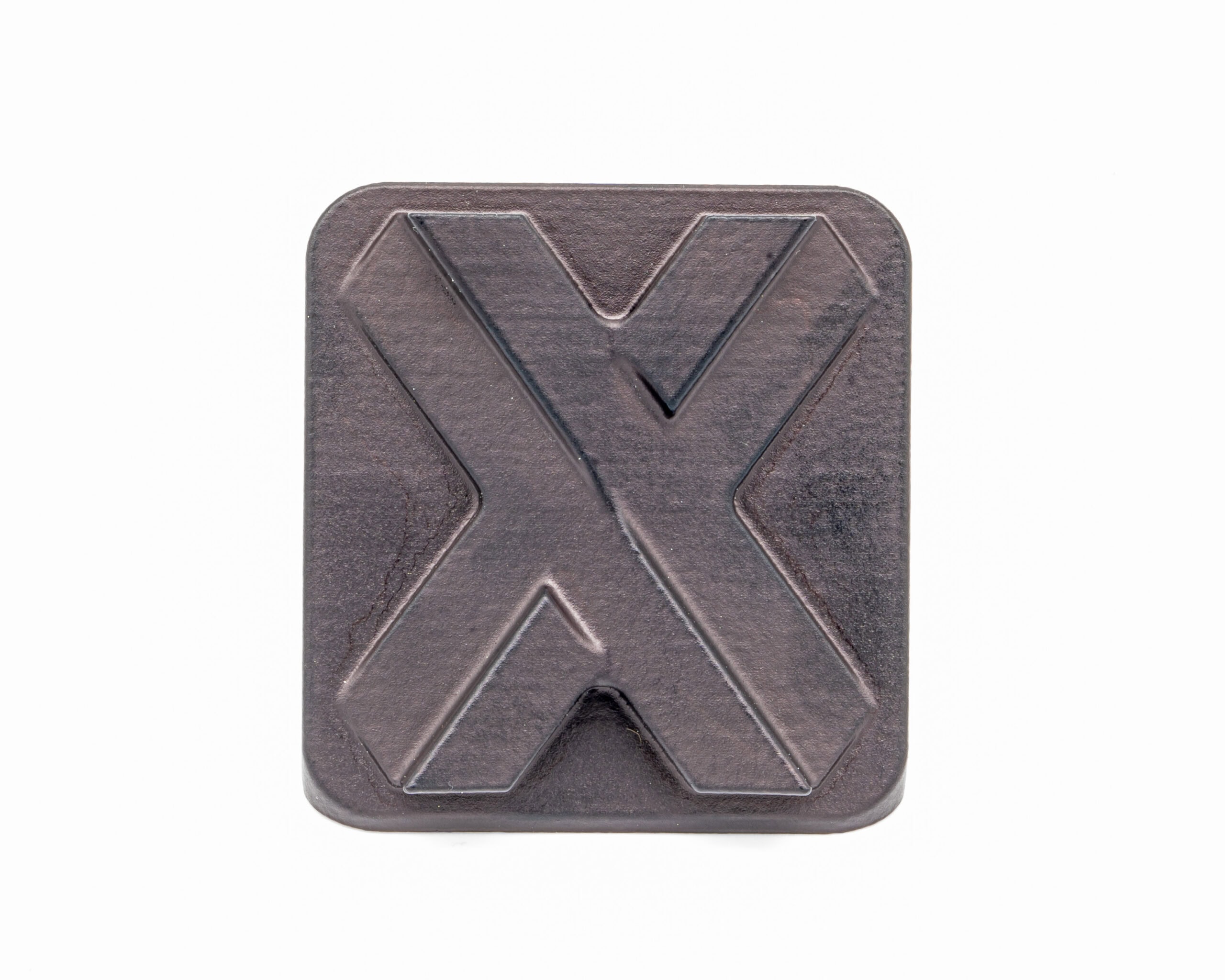
0 Nikolaus Mroncz22.04.2024 at 12:23Xometry Engineer…X has about 10mm
 Automatically translated from: DeutschSee original0in reply to: Letters in MJF 3D Printing After Steam Smoothing
Nikolaus Mroncz19.04.2024 at 14:22Xometry Engineer
Automatically translated from: DeutschSee original0in reply to: Letters in MJF 3D Printing After Steam Smoothing
Nikolaus Mroncz19.04.2024 at 14:22Xometry EngineerHello Tilmann 98,
Thank you very much for your question and even more so, for your activity and contributing your knowledge on our platform!!
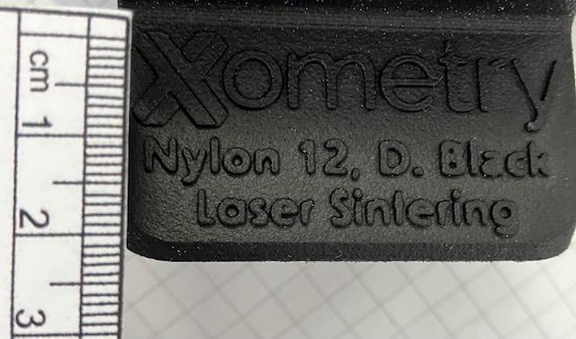
The proportion of depth/height to width is somewhat unusual and despite the fact that we would prefer to vape with medium strength, I would prefer the raised text.
Here is a good example of the behaviour of sharpness in inscriptions

and a link to the article:
https://xometry.pro/de/artikel/3d-druck-dampfglattung/
VG
Automatically translated from: DeutschSee original0in reply to: Letters in MJF 3D Printing After Steam Smoothing
Nikolaus Mroncz12.04.2024 at 13:31Xometry EngineerUnfortunately shore 50A is rare. There is shore 50 in SLA standard, but you cannot chose it, you need to choose custom and the material is Formlabs elastic 50A

-
This reply was modified 1 year, 11 months ago by Nikolaus Mroncz.
-
This reply was modified 1 year, 10 months ago by Uliana Krayneva.
0 Nikolaus Mroncz09.04.2024 at 13:52Xometry EngineerHello Mr. Schmidt,
PA12 in itself is very chemically resistant. The chemical steam smoothing seals the pores and leads to higher resistance. I consider it suitable for use under seawater conditions.
Automatically translated from: DeutschSee original0 Nikolaus Mroncz09.04.2024 at 12:19Xometry EngineerHello Luca,
I can only agree with Tilmann 98 here. SLS parts are generally of high quality and have a density of almost one in PA12, in MJF also above one. The difference is about 10%. Another possibility to minimize creep would be PA12GF (glass filled). This PA12 has a 30% glass content and is harder, but then tends to break more quickly if excessive forces are applied.
Automatically translated from: DeutschSee original0in reply to: SLS – Design Tips
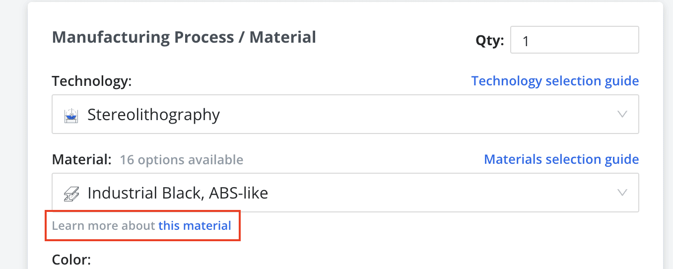
Nikolaus Mroncz28.03.2024 at 11:57Xometry EngineerHi and thank you for a good question. Normally the question is what is the difference in industrial and standard. Standard is using Desktop machines, industrial, industrial machines. But the resin, is it so different? Not really! They could be quite similar! To see how much they would differ, you can click on the link below the material. This will lead you to the datasheet.
 0in reply to: Standard and industrial SLA materials
Nikolaus Mroncz27.03.2024 at 12:06Xometry Engineer
0in reply to: Standard and industrial SLA materials
Nikolaus Mroncz27.03.2024 at 12:06Xometry EngineerHey, here you have an overview of the 3D technologies we offer and their design limitations:
-
This reply was modified 2 years ago by Nikolaus Mroncz.
0in reply to: Recommended wall-thickness for FDM
Nikolaus Mroncz26.03.2024 at 09:13Xometry EngineerHello and thank you for your question. Actually, I have already made some experiments in metal printing. I would be happy to discuss this with you. If you want, you can contact me directly (nmroncz@xometry.de). Generally, I would say that the correct proportion is crucial. A grid structure at an angle of, for example, 45° increases the strength. Also, reducing sharp edges at the docking points is important to prevent break points. Best regards
Automatically translated from: DeutschSee original0 Nikolaus Mroncz22.03.2024 at 16:54Xometry EngineerHello, there is no general answer here, so better to evaluate the concrete part.
We recommend a minimum wall thickness of 1-2mm for unsupported walls in FDM, but this depends also to the overall design.
BR
2in reply to: Recommended wall-thickness for FDM
2
Nikolaus Mroncz22.03.2024 at 14:48Xometry EngineerFor this, please try our Instant Quoting Engine. You can upload the part on our website and see immediately the price, also if you change the technology. It depends on volume and design of the part, so not to answer, the one or the other.
-
This reply was modified 2 years ago by Nikolaus Mroncz.
0in reply to: Vapor smoothed and dyed black part MJF vs. SLS
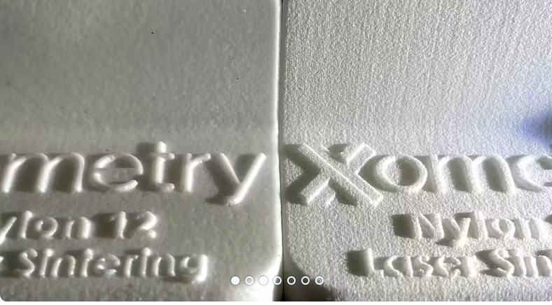
Nikolaus Mroncz22.03.2024 at 14:12Xometry EngineerThanks for your questions!
Here I share some images, how the parts may look:

The first is SLS and the second MJF. Finally the parts may look quite similar, still it also depends on the design.
0in reply to: Vapor smoothed and dyed black part MJF vs. SLS
Nikolaus Mroncz21.03.2024 at 16:39Xometry EngineerPETG is a strong material and also good in elongation at break, but be aware that in FDM the properties in Z – direction are always weak. So in practice, it would be not so much dependable and weaker in Z- direction then the suggested above.
-
This reply was modified 2 years ago by Nikolaus Mroncz.
0 Nikolaus Mroncz21.03.2024 at 14:50Xometry EngineerHi Robert, sure.
PA12 or PA11 in SLS or MJF works best here. PA11 is the more durable of them.
BR
1in reply to: Materials suitable for snap-fit features in 3D printing
1
Nikolaus Mroncz20.03.2024 at 15:10Xometry EngineerDear,
SLS parts are good for painting.
You can also order spray painted parts directly at Xometry, what I also think, is the best option to achieve a constant result.
0 Nikolaus Mroncz19.03.2024 at 16:26Xometry EngineerTo go more into detail, it would be better to know the product, there also not every design is suitable.
Please contact me via mail: nmroncz@xometry.de
0in reply to: Food contact safe manufacturing
Nikolaus Mroncz19.03.2024 at 15:37Xometry EngineerDear michele.gennaro,
we can produce food compliant parts in SLS and PA12 or PA11.
Gladly I can provide you an example of an certificate before your order, showing it is also compliant with EU regulation.
Just leave a message in your inquiry, so I can provide.
The right choice on our webside would be SLS/ Nylon Food Grade
2in reply to: Food contact safe manufacturing
2
Nikolaus Mroncz19.03.2024 at 15:18Xometry EngineerQuick Clear Coating is a spray painting with clear spray. It prevents the parts from the SLA typical yellowish and also to get fast brittle. It is very effective!
1in reply to: UV exposure impact on brittleness of SLA 3D parts
1
Nikolaus Mroncz18.03.2024 at 11:58Xometry EngineerDear 3D Geek,
in MJF you can print flexible parts in TPU. We use 2 different ones here: Esthane TPU and BASF Ultrasint. Esthane has shore 95 and Ultrasint shore 88. If you prefer one of them, please add this to the comments, if you order. To have it water resistant, you need to add a post processing, which would be vapour smoothing. It works best with Ultrasint.
BR
1in reply to: TPU with MJF 3D printer
1
Nikolaus Mroncz18.03.2024 at 11:50Xometry EngineerHi Stefan,
for prototypes, SLA still is fine. I would say, you can observe an aging and a change in proberties (by getting brittle) after a couple of month. I don’t see big differences between the standard resins here. To prevent this, you can , for example, spray paint the parts. Also SLS/ MJF combined with vapour smoothing could be an option.
BR
1in reply to: UV exposure impact on brittleness of SLA 3D parts
1
Nikolaus Mroncz14.03.2024 at 13:45Xometry EngineerDear Kris.Mel,
Thank you for your question.
For SLA, we recommend a wall thickness of at least 0.6 mm for non-supporting walls.
You can find more information here:
https://xometry.pro/de/article/3d-printing-sla-design-guidelines/
1in reply to: Wall thicknesses for SLA (100 mm high) – any tips?
1
Nikolaus Mroncz13.03.2024 at 16:06Xometry EngineerEngineerNearby38We conducted experiments in-house with SLS and MJF 3D prints and we actually have some concrete data to share. We measured the surface roughness of SLS prints with different surface finishes: PA12 raw part (approximately 8 µm), PA12 bead blasted (4.5 µm) vs PA12 vapour polished + dyed black (2.5 µm). And we did the same for MJF prints and 5 other 3D printing technologies. I would recommend you to check our article on this topic: https://xometry.pro/en-eu/articles/3d-printing-surface-roughness/
-
This reply was modified 2 years ago by Nikolaus Mroncz.
1in reply to: Surface roughness in 3D printing
1
Nikolaus Mroncz13.03.2024 at 11:47Xometry EngineerTechCrafterThe roughness of a surface depends on a variety of factors, including the design of the part, the manufacturing process used to create it and the manufacturer. Even if you select a 3D printing technology with a supposedly great surface finish, the parts might still present some stepping marks or have a slightly curved surface, causing a decreased surface roughness quality.
You can keep in mind that the MJF process produces a less porous surface compared to SLS, and has a smoother texture. And as you said, a near-perfect poreless surface can be achieved in both MJF and SLS thanks to post-processing operations like vapour smoothing and bead blasting.
0in reply to: Surface roughness in 3D printing
Nikolaus Mroncz13.03.2024 at 10:32Xometry EngineerEvgeny MDesigning threads into the part is a valid option only for MJF and SLS processes – for other technologies, the thread might not be perfectly printed and will probably need additional post-processing operations to properly rework its shape.
1in reply to: Thread Cutting in 3D Printing
1
Nikolaus Mroncz13.03.2024 at 10:13Xometry EngineerThere are two types of surface finishes available for parts printed with nylon (with either SLS or MJF technologies):
- Post-processing operations that aim to smooth the surface of the parts, for example, vapour smoothing, bead blasting or media tumbling
- Colour finishes to better customize the parts, like dyeing and spray painting
Both categories are mostly applied for aesthetic purposes. We have a detailed overview of surface finishes for 3D printing on the website, as well as a page dedicated to Nylon PA 12:
0in reply to: Finish options for nylon in 3D printing
Nikolaus Mroncz12.03.2024 at 05:47Xometry EngineerHey Lars,
1. Larger parts could be devided and glued after printing (we could do it also, if it makes sense in shipping)
2. The surfaces need to be clean and powder free
3. The choice of the right glue is mandatory. A super glue is fine, but better to take a thicker one, which is a bit flexible, to outhold vibrations or a small hit should be no problem then.
BR
1in reply to: Gluing together SLS parts for larger builds?
1
Nikolaus Mroncz09.02.2024 at 10:08Xometry EngineerDesigning for CNC machining requires careful consideration to optimize the process for efficiency and high-quality results. Here are some critical design tips:
- Material Selection: Choose the right material for your application, considering factors such as strength, durability, and machinability. Common materials for CNC machining include aluminum, steel, brass, and various plastics.
- Tolerances and Clearances: Specify clear tolerances for dimensions and clearances for fit and assembly. Tighter tolerances can be more precise but may increase costs, while looser tolerances can be more cost-effective for less critical features.
- CNC Tool Selection: Work closely with your CNC machinist to select the appropriate cutting tools and toolpath strategies. The right tool and cutting parameters can significantly impact the surface finish and production speed.
- Avoid Overly Complex Geometries: Keep your design as simple as possible. Complex geometries with many sharp corners or intricate features can increase machining time and costs. Simplify where feasible.
- Internal Fillets and Radii: Use internal fillets and radii for sharp corners. This not only improves part strength but also makes machining smoother and less prone to tool breakage.
- Tool Access: Ensure that the tool can reach all areas of your part without interference. This may require modifying the design to avoid deep pockets or narrow channels that the tool can’t access.
- Machinability: Consider the machinability of the material. Some materials are more challenging to machine than others, which can affect tool wear and machining time.
- Avoid Undercuts: Minimize or eliminate undercuts in your design, as they may require additional setups and increase complexity.
- Part Orientation: Think about how the part will be fixtured and oriented during machining. Design features should allow for efficient clamping and minimal deflection during cutting.
- Draft Angles: If your design includes molded or cast features, incorporate draft angles to facilitate easy removal from the mold or die.
- Surface Finish: Specify the desired surface finish on critical surfaces. This can help the machinist select appropriate tooling and machining parameters.
- Avoid Thin Walls: Thin walls can be fragile and prone to distortion during machining. Ensure that wall thicknesses are adequate for the material and part function.
- Counterbore and Counterbore Depths: Use counterbores to create recesses for fasteners. Ensure proper depths for screws, bolts, or other fastening components.
- Deburring and Edge Breaks: Design parts with edges that are easy to deburr, as sharp edges can be a safety concern and increase labor requirements.
- Communication with Machinist: Maintain open communication with your CNC machinist. They can provide valuable insights into optimizing your design for efficient machining.
- Prototyping and Testing: Before proceeding with a large production run, create prototypes to test your design. This can help identify potential issues and improve the final product.
By following these design tips, you can help ensure that your CNC machining project is cost-effective, efficient, and results in high-quality parts that meet your specifications and requirements. Collaborating with experienced machinists and manufacturers is also key to achieving the best results in CNC machining projects.
0in reply to: Tips for designing for CNC machining
Nikolaus Mroncz07.02.2024 at 10:34Xometry EngineerIn addition to the thicker sizes available for aluminum 6061 sheets mentioned earlier, thinner sheets are also widely available in Europe. Suppliers such as TW Metals stock aluminum 6061 in various thin thicknesses. The available thicknesses for these sheets include:
- 0.0120 inches (0.305 mm)
- 0.0160 inches (0.406 mm)
- 0.0200 inches (0.508 mm)
- 0.0250 inches (0.635 mm)
- 0.0320 inches (0.813 mm)
- 0.0400 inches (1.016 mm)
- 0.0500 inches (1.27 mm)
- 0.0630 inches (1.6 mm)
- 0.0710 inches (1.803 mm)
- 0.0800 inches (2.032 mm)
- 0.0900 inches (2.286 mm)
- 0.1000 inches (2.54 mm)
- 0.1250 inches (3.175 mm)
- 0.1600 inches (4.064 mm)
- 0.1900 inches (4.826 mm)
- 0.2490 inches (6.324 mm)
These are available in different tempers and are certified to various standards including ASTM B209. This broad range ensures that for most applications, whether it be for aerospace, automotive, or consumer goods, there is a suitable thickness of aluminum 6061 sheet available in the European market. Combining these with the thicker sizes provided by suppliers like Metalex, it’s clear that manufacturers and engineers have a wide spectrum of thicknesses to choose from for their specific requirements.
0in reply to: Sheet metal material thickness Alu 6061
Nikolaus Mroncz07.02.2024 at 10:33Xometry EngineerIn Europe, specifically from suppliers like Metalex in the UK, aluminum 6061 is available in a wide range of thicknesses. The stocked thicknesses start from 1/4″ (6.35mm) and go up to 330mm (8 inch). This includes a variety of specific sizes in between, such as 8mm, 20mm, 1″ (25.40mm), and goes up to substantial sizes like 305mm and 330mm, catering to a broad range of industrial needs. The aluminum plates are available up to 4000mm x 2000mm in size.
1in reply to: Sheet metal material thickness Alu 6061
1
Nikolaus Mroncz06.02.2024 at 12:51Xometry EngineerCNC machining sharp internal corners can be challenging due to the inherent limitations of machining processes and the tool geometry. Here are several methods that can be employed to tackle this issue:
1. Adding reliefs: This is a commonly used method where certain shapes are added to the corners to accommodate the roundness of the milling tool. There are various types of reliefs such as:
- A hole centered in each corner: This is the cheapest solution and involves placing a hole at the corner where two internal edges meet
- Half-Moon relief: A slightly more expensive option than the hole, shaped like a half-circle at the corner
- Internal Radii: This is another form that is equivalent in cost to the half-moon and involves creating a rounded internal corner
2. Avoidance of sharp corners: Where possible, the design can be altered to avoid sharp corners altogether. Instead, radii are included on all internal edges, using an end mill with a radius slightly smaller than the added edge radius
3. Dog-bone or T-bone fillets: These are specific types of undercuts that can be used to extend the corner shape beyond the cut area. This allows the milling tool to either complete a full rotation or to back up slightly to create a sharp angle following the tool path
4. Electrical Discharge Machining (EDM): For cases where sharp internal corners are essential and cannot be avoided, electrical discharge machining can be used. This process involves creating sharp corners by eroding the material with electrical discharges. It is noted, however, that EDM tends to be an expensive method
It is generally suggested to design parts in a way that avoids the need for sharp internal corners due to the complexity and additional cost involved in manufacturing them. The best approach often involves collaboration between designers and machinists to find a manufacturable compromise that meets the design requirements while being feasible to machine.
2in reply to: CNC machining of sharp internal corners
2
Nikolaus Mroncz20.11.2023 at 14:11Xometry EngineerIf you are looking for 3D printing materials in UL 94 V-0, with highest grade of flame-retardancy, then FDM ULTEM 1010 and ULTEM 9085 are the most suitable ones. PA 2241 FR is another UL 94 V-0 suitable option if you’re considering SLS as a printing technology. For FDM, ABS industrial-grade is also flame-retardant 94 HB (with the lowest grade in the UL 94 classification).
-
This reply was modified 2 years, 4 months ago by Nikolaus Mroncz.
1in reply to: 3D printing with flame-retardant material
1
Nikolaus Mroncz20.11.2023 at 13:59Xometry EngineerHere, the choice largely depends on what type of material (metal or plastic) your part needs to be made of.
For plastic parts, I would recommend the following materials:
- ULTEM 9085 and ULTEM 1010 for FDM
- PA 12 for SLS or MJF
- Heat-resistant ones like PC for SLA after thermal post-processing
- CE 221 (Cyanate Ester) for Carbon DLS
For metal parts, the heat-resistant materials I would recommend for DMLS are:
- Aluminium AlSi10Mg
- Stainless steel 316L
- Inconel 718
You can check out our dedicated article on heat-resistant materials for 3D printing and compare the properties of the materials.
0in reply to: Heat resistant 3D printing material
Nikolaus Mroncz20.11.2023 at 13:47Xometry EngineerWhen combined to HP MJF technology, PA 12 is indeed water-resistant. But if you want to be 100% sure that the material is watertight (and not just water-resistant), we recommend you to apply a vapour smoothing finish to the PA 12 printed parts.
-
This reply was modified 2 years, 4 months ago by Nikolaus Mroncz.
1in reply to: Is PA 12 a watertight material?
1
-
This reply was modified 1 year, 8 months ago by