Compression molding is a cornerstone among manufacturing processes, providing a robust method for crafting intricate components with precision and reliability. This versatile technique involves the use of heat and pressure to shape raw materials into desired forms, making it a popular choice across various industries.
Compression Molding Process
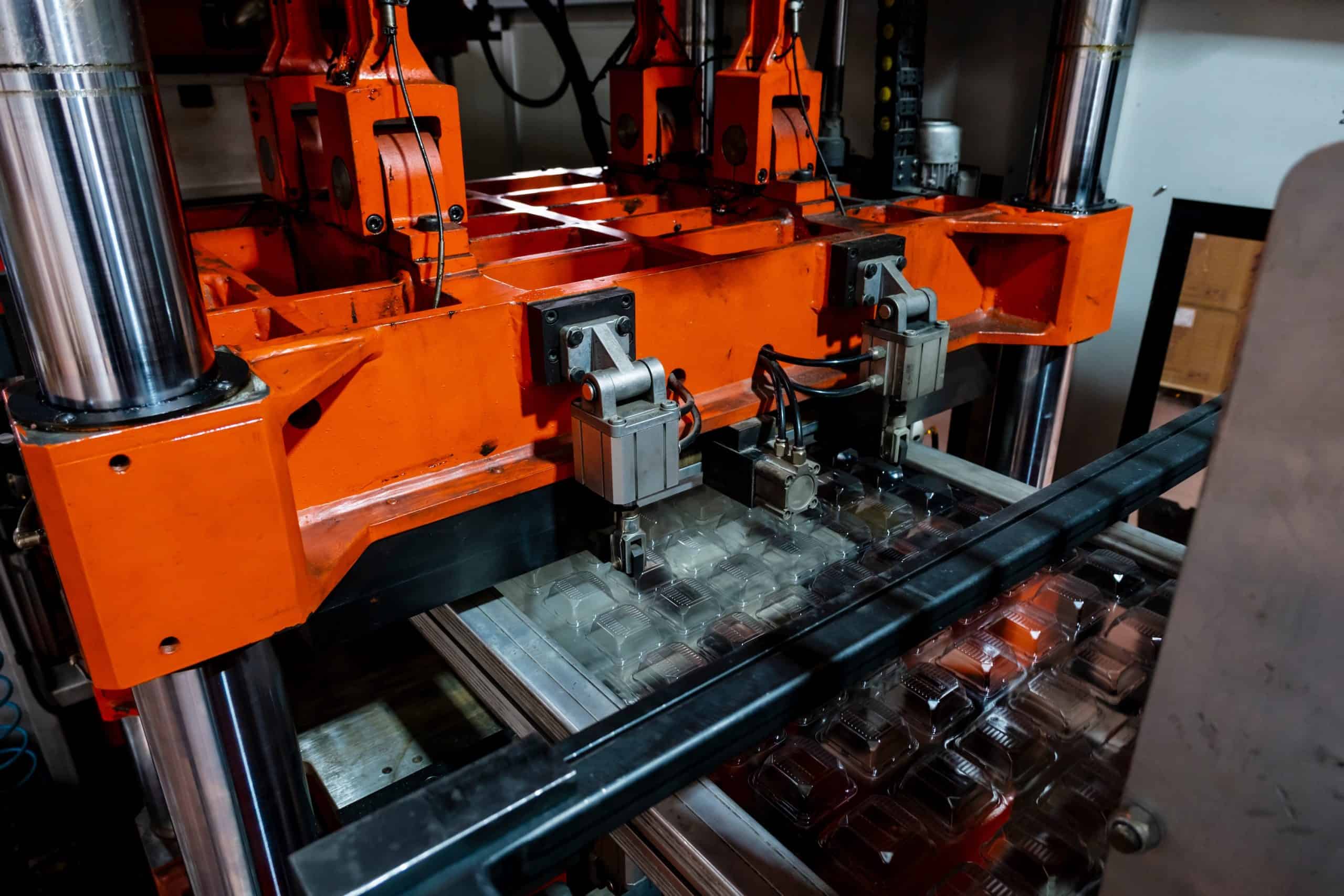
The fundamental mechanics of compression molding are straightforward. Compressive forces are applied to shape a deformable material charge which then hardens through curing before its removal from the mold.
The process starts with the material charge being introduced into the mold. A powerful press then applies pressure to the mold, compressing the charge, and filling the mold cavity with material.
Once the material has been fully distributed within the mold, it’s then subjected to a curing period. During this stage, the heat and pressure cause the material to undergo a chemical transformation, hardening into the intended shape.
Post-curing, the compression molded part is carefully extracted from the mold. Any excess material, known as flash, which may have seeped out during the process, is trimmed away in the post-processing stage.

Compression Molding vs. Injection Molding
Despite similarities with injection molding, compression molding holds a distinguishing feature. Compression molding involves the molds being closed around the charge, in contrast, when injection molding the charge is injected into a closed mold cavity.
Injection molding, often a preferred choice for complex parts, requires shorter cycle times rendering it faster and more cost-effective for large-scale production.
Compression molding, being a lower-pressure process offers reduced tooling costs making it ideal for simpler designs and smaller to medium production runs.

Compression Molding Design Tips
How you design parts for compression molding is significantly less complicated than designing for injection molding, as there is almost no shrinkage, warpage or sinkage to contend with. But we recommend considering the following design guidelines:
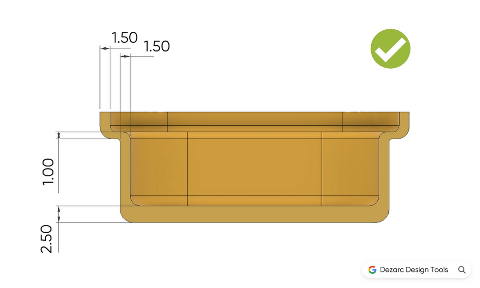
Wall Thickness
One of the advantages designers and engineers have when working with compression molding is the flexibility of wall thickness. Unlike many other manufacturing processes, compression molding doesn’t impose stringent restrictions on the minimum or maximum wall thickness, opening the door for increased design flexibility.
In compression molding, it is possible to achieve both thin and thick walls within the same part without compromising the structural integrity or dimensional accuracy of the final product.
While this freedom is liberating, careful consideration of wall thickness is still crucial. It can have a big influence on the cost of a part due to the increased curing time & material usage associated with thick-walled parts.
- Optimal wall thickness: 1.5mm – 6mm
- Minimum wall thickness: 0.5mm
- Maximum wall thickness: 12mm +
Undercuts
Undercuts – recesses inaccessible from the mold’s open ends – can often complicate the molding process as they usually necessitate side actions or collapsible cores for ejection.
Since most parts formed by compression molding use elastomeric materials like silicone, undercuts are achievable without adding intricate mechanical features.
However, two critical considerations arise when designing compression molded parts with undercuts:
- The feasibility of the undercut’s formation through EDM or CNC machining. If this isn’t feasible, a multi-part mold tool that is pre-assembled might be necessary, increasing tooling costs and shortening tooling lifespan.
- The ease of part removal from the mold. If the part can’t be removed without causing damage or requiring excessive effort, labor costs rise. In the worst-case scenario, where the part cannot be removed at all without inflicting damage, the toolmaker may need to create a more complex mold. This might involve side actions, a middle plate, or collapsible cores, all of which escalate tooling costs and reduce tooling life.
Whether or not a part can be removed from the mold will depend on a handful factors specific to your application such as the material properties & part geometry. It is always best to reach out to your supplier for their opinion during the design process to avoid any issues down the line.

Draft
In establishing the minimum draft for a part, the rigidity of the intended material is the primary consideration. It’s entirely feasible to mold elastomeric components with zero or even negative draft.
The tradeoff is the labor expense associated with extracting the part from the mold. Design for Manufacture (DFM) is about optimizing every stage of the manufacturing process, from tooling to assembly.
By incorporating draft into parts the removal process can be streamlined, resulting in lower manufacturing costs.
Suggested draft angles:
- For walls shorter than 25 mm: 1 – 2° draft is recommended
- For walls taller than 25 mm: 2 – 4° draft is advised
Snap Fits
We could write an entire design guide just on the various types of snap-fits and how to design them, but in this section we will just cover the basics.
Cantilever snap fits: The conventional cantilever snap fit is seldom employed in conjunction with elastomeric materials.
Annular snap fits: These types of snap fits are perfectly suited for components made from elastomeric materials, a trait that stems from the material’s inherent flexibility. As their name suggests they are characterized by their circular or ring-like structure.
Annular snap fits utilize the elastic properties of the material to enable assembly and disassembly. When the parts are pushed together, the protruding edge of the snap fit deforms to allow assembly and then rebounds once in place, holding the parts together securely.

Insert Molding
A common feature in the molding industry, “insert molding”, involves the positioning of a pre-made part, often metallic, into a mold. This mold is subsequently filled with molding material, which upon solidification, creates a component integrating the inserted part.
For effective insert molding with compression molding, two key considerations must be addressed:
- The impact of compressive forces: Significant force is necessary to ensure the complete filling of the cavity. If the encapsulated materials are delicate, it might suffer damage due to these repeated forces.
- Maintaining insert position: During the molding process, securing the position of the insert is crucial. This is typically achieved by using compression molds pin that hold the insert externally, leading to a section that remains unfilled.
Provided these points are given due consideration, compression molding can be used to encase a wide range of elements – from threaded inserts to antennas – within a thermoset resin.
Common Inserts:
- Threaded Inserts: Typically made from brass or steel. They allow for the repeated use of durable threads in rubber parts
- Weights: Weights are frequently added to molded parts either for a functional purpose or to add a premium feel
- Printed Circuit Boards (PCB): These electronic boards can be encapsulated in material to form durable & waterproof electronic assemblies
- Wiring: Electrical wiring can be encased in material to form durable wiring harnesses
- Buttons: An elastomeric sheet of multiple buttons can be formed to control electrical systems

Texture
Texture isn’t just about aesthetics—it’s a significant functional feature that can drastically affect product performance. Whether you’re seeking to improve grip, camouflage manufacturing marks, or create a certain visual effect, texture plays a pivotal role in component design.
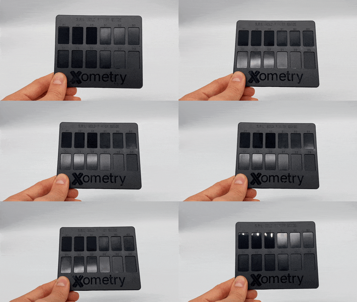
When it comes to defining the texture for a molded part, the industry generally refers to two primary standards: the Society of the Plastics Industry (SPI) standards and the Association of German Engineers (VDI) standards.
Compression molding allows for brilliant texture reproduction of the full range of SPI & VDI textures from rough EDM finishes to shiny diamond buff finishes. Our compression molded elastomer hardness sample range features 4 types of SPI texture zones that are a brilliant display of how well compression molding can reproduce textures.
SPI Texture mini-guide:
- Glossy – SPI A1-3
- Semi-gloss – SPI B1-3
- Matt – SPI C1-3
- Textured – SPI D1-3
Compression Molding Material Selection
Here are the two main categories of material used in compression molding:
- Elastomer: Any rubbery material that is capable of recovering to its original shape after significant deformation
- Thermoset: Thermoset polymers are heat-resistant materials that undergo an irreversible chemical reaction when cured, resulting in a rigid structure that maintains its form even under high temperatures.
Thermoset Elastomers
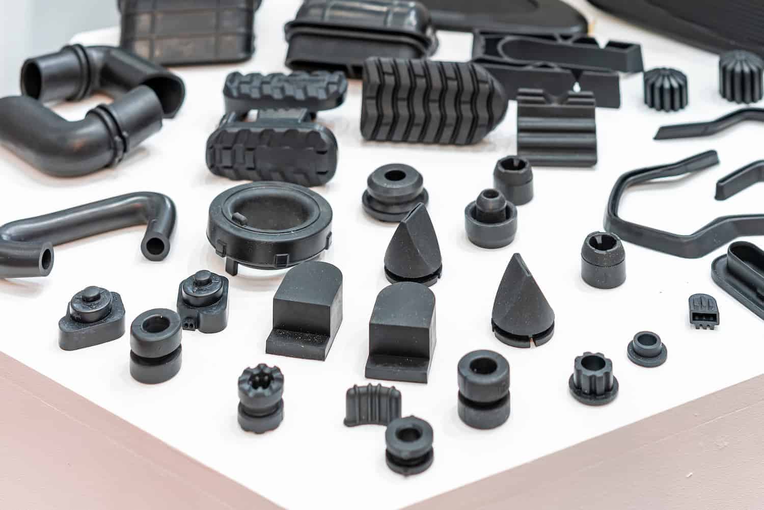
This is the most common category of compression molded materials and is used in a range of applications from O-ring & gasket seals to food-safe containers. Because thermosets do not melt they are perfect for high-temperature sealing applications.
The hardness (or softness) of elastomers is measured by a tool called a durometer. This measures the resistance of a material to indentation. The Shore A scale is used to communicate the required hardness of silicones.
Typically compression molded elastomer parts will fall between Shore A20 and Shore A80 with A20 feeling similar to a gel-insole and shore A80-like tyre tread. To get a hands-on feel of elastomer hardness check out our sample kit.
- Silicone: Silicone is a commonly used thermoset elastomer. Not only is it temperature-resistant but it is also abrasion-resistant, chemical-resistant, food-safe & biocompatible
- Nitrile: A very common material in industrial sealing applications thanks to its oil resistance
- Viton: Used in high-temperature automotive applications thanks to its fuel resistance styrene-butadiene rubber: Used in wet applications due to its water resistance
Thermoset Plastics
Compression molding allows for the formation of strong composite materials through the combination of polymer resin, fibers, stabilizers, and filler.
There are two main composite resins used in the automotive industry known as sheet molding compound (SMC) and bulk molding compound (BMC).
Common thermoset resins:
- Epoxy Resin: Excellent mechanical strength
- Polyester: Excellent chemical resistance
- Polyurethane: Can be formulated to produce a wide range of material characteristics
The use of thermoset materials is a controversial topic as these types of plastics cannot be easily recycled or disposed of sustainably. When the application permits they should be substituted for more sustainable plastics.
Conclusion
In wrapping up, understanding and implementing effective design strategies in compression molding can significantly impact the efficiency and quality of manufacturing processes. By focusing on design principles and material selection, engineers and manufacturers can harness the full potential of this versatile technique.
 Europe
  Türkiye
  United Kingdom
  Global

 Login with my Xometry account
  0
0




Comment(0)